
Single-line power supply diagram - purpose and types
In accordance with the "Rules for the technical operation of electrical installations of consumers", a single-line power supply diagram is one of the types of executive documentation, which must be available from an organization and a private person operating power grids and equipment without fail. In this article by the homemaster.techinfus.com/en/ edition, we will describe in detail what such a scheme is, what it should include, as well as the rules for its design in accordance with all regulatory documents.
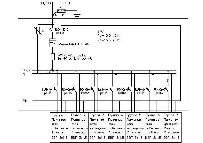
Single-line power supply diagram of a country house
The content of the article [Hide]
What is a single-line power supply diagram and why is it needed
A single-line power supply diagram is a technical document that displays all the elements of the facility's electrical network, indicating their characteristics and parameters, as well as the installed and calculated capacity of the facility as a whole. The term "single-line" means that all electrical connections existing on the object, regardless of their phase, are displayed on the diagram as a single line. The rules for the design of single-line diagrams are regulated by GOST 2.702-2011 "Unified system for design documentation (ESKD). Rules for the implementation of electrical circuits ". The main purpose of such executive documentation is to provide information and visual perception of the configuration of the electrical network of the facility, which is necessary for making decisions during the operation of the energy sector.
An example of the design of a single-line power supply diagram of an industrial enterprise
Types of single-line electrical circuits
Depending on the stage at which work on the creation of the electrical network of the object is drawn up a single-line diagram, its type and intended purpose depend.At the stage of development of project documentation, a single-line calculation diagram is drawn up, which serves as the main document for calculating the parameters of the power supply system. It is this document that is necessary for subsequent approvals with the authorities issuing technical conditions for connecting the construction object to the existing electrical networks, which are the power grid organizations at the location of the facility-consumer of electrical energy.
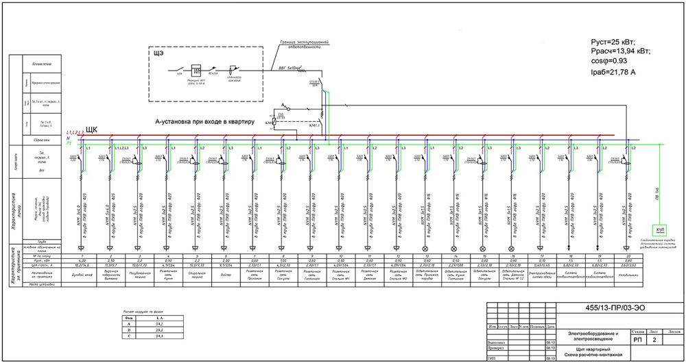
Calculation scheme of the apartment board of a country house
At the stage of operation of the facility, single-line executive diagrams are drawn up, which display all the changes made to the configuration of the electrical network during its use. This may be due to the modernization of the equipment used or its replacement, the addition of new capacities or a change in the configuration of trunk and group lines. At large facilities, where the power supply system is subdivided into several levels, single-line diagrams are drawn up for each consumer group: "the facility as a whole - workshop - site", etc. Initially, a drawing is made showing the substations (TP) and the configuration of the networks that unite them, then the diagram of the TP or MSB (main switchboard) and then - each power or lighting panel available at the facility.
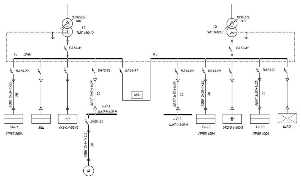
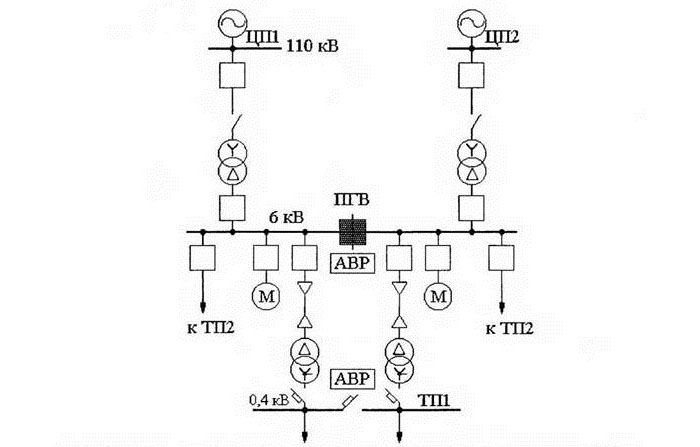
Executive diagram of 2-transformer substation
On the basis of single-line ones, other electrical circuits of the power supply system are being developed: structural and functional, principle and installation.
Design principles for a single-line power supply diagram
When developing and drawing up as-built documentation, it is necessary to comply with the requirements for similar documents reflected in the regulatory literature, as well as PTEEP and PUE ("Electrical Installation Rules").
What should include a single-line power supply diagram
The following information should be reflected on single-line power supply diagrams, namely:
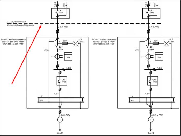
Displaying the balance zone on the object's power supply diagram
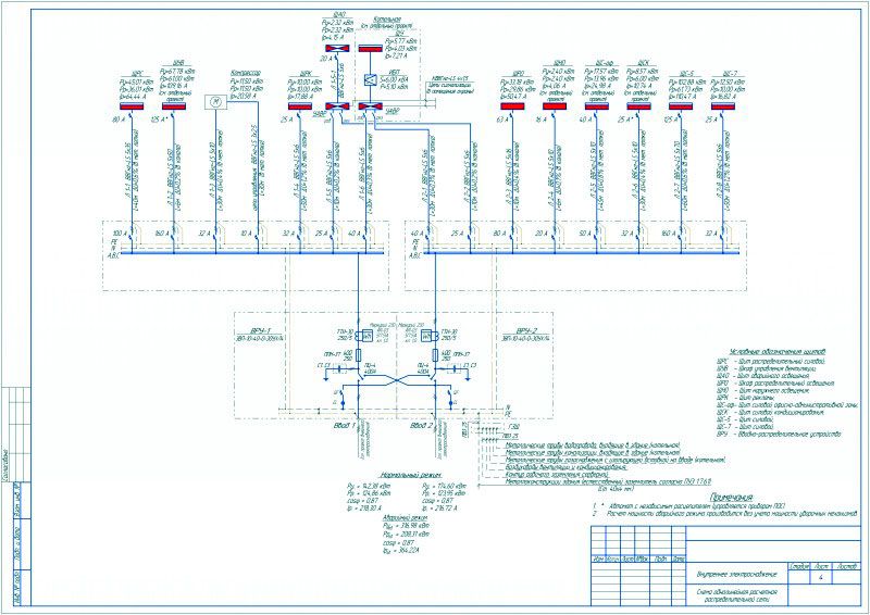
A variant of the execution of the calculated single-line power supply diagram of an administrative building
Design stages
The presence of a single-line power supply diagram is a prerequisite for obtaining permission to connect the construction object to the networks of the power supply organization, therefore, before proceeding with its development, it is necessary to request technical conditions.
In this regard, all work on the design of the power supply scheme can be divided into several stages:
- Request and receipt of technical specifications;
- Development of a single-line power supply diagram based on the documents received;
- Coordination of the developed documentation in the organization that issued the technical specifications.
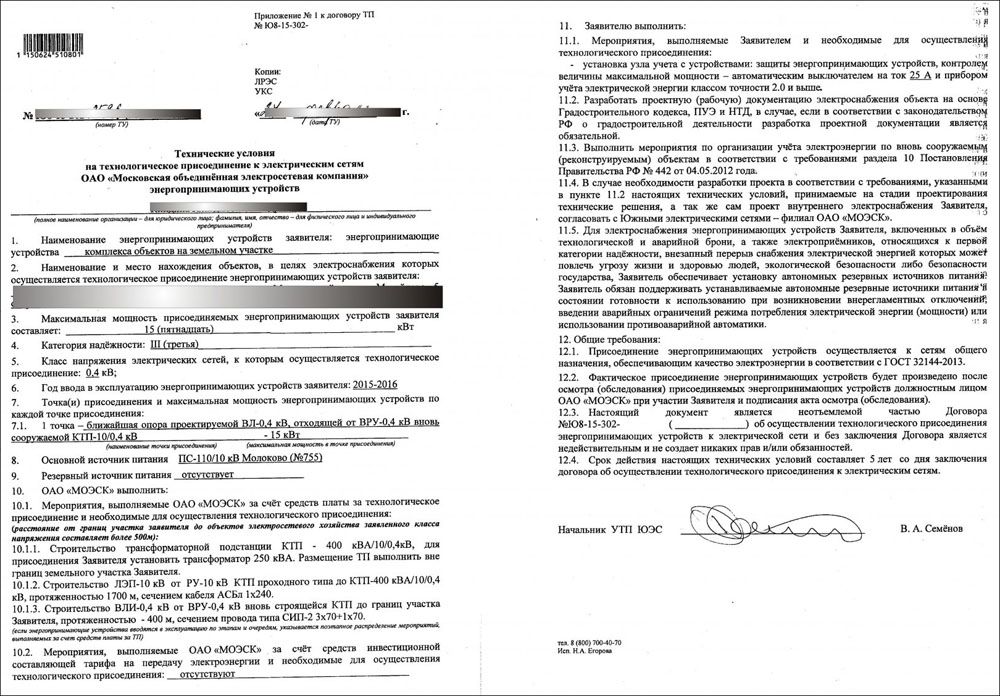
Option for registration of technical specifications for power supply
Registration rules, GOST requirements
When drawing up a single-line power supply diagram, it is necessary to comply with the requirements of GOSTs governing this process, namely:
The design option for a single-line power supply diagram in accordance with these GOSTs is shown in the following figure.
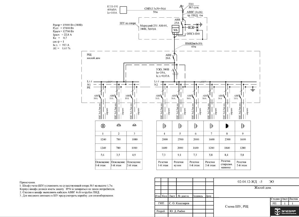
Calculated single-line diagram of the power supply of a residential building
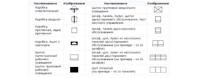
Symbols used in drawing up single-line diagrams
All elements of the power supply system are displayed on the diagram in the form of graphic images, which are regulated by the regulatory literature indicated in the previous section of the article. Electrical boxes and cabinets for various purposes are depicted as follows.
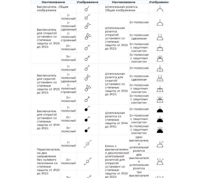
Wiring accessories (sockets and switches), depending on the design and type of execution, are displayed like this
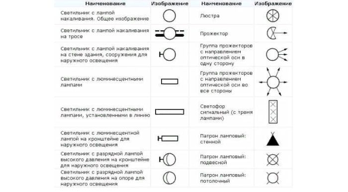
Electric lighting devices are depicted as follows
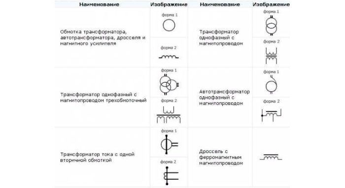
Power transformers and current transformers are depicted as follows
Electrical measuring instruments have the following appearance on the power supply diagrams, in accordance with GOST

The intersection of electrical lines and wiring connections, as well as grounding are as follows

Switching devices (circuit breakers and starters, short-circuits and separators, as well as other devices) are depicted as follows
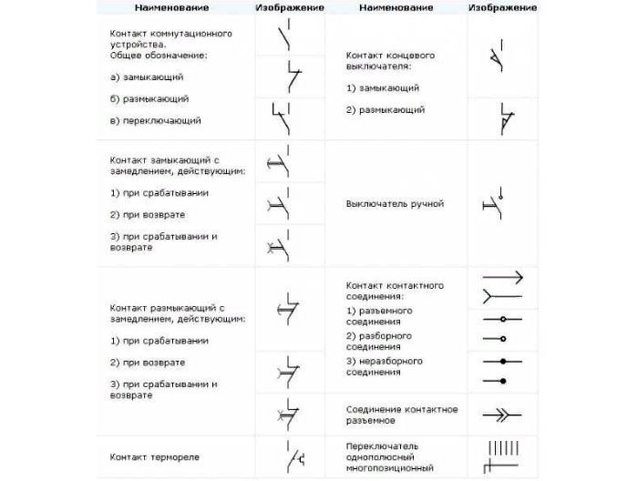
In order to find out how to correctly draw up the executive documentation, it is necessary to study all the requirements of GOSTs or use a special computer program that will take into account all these requirements in automatic mode when using it
Programs for execution of executive documentation
Currently, in order to draw up the developed single-line diagram in accordance with the requirements of GOST, it is enough just to have a personal computer and special software that allows you to do this work. There are several types of computer programs designed for these purposes:
- "Compass-Electric" - a free program, quite easy to use, is popular among engineers and technicians working in the services of the chief power engineer of enterprises of various profiles.
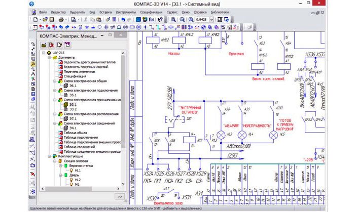
Drawing up an electrical diagram using "Compass-Electric"
- Microsoft Visio - a free program that people usually use when drawing up a power supply scheme for a private house or apartment on a one-time basis.
- "1-2-3 scheme" Is a free program popular with students and aspiring technicians.
- "Eagle" - the program is implemented in free and paid packages, differing in their technical capabilities.
- DipTrace - the program is used for drawing up electrical circuits and drawing printed circuit boards used in the manufacture of electronic devices.
- "AutoCAD Electrician" - one of the most famous and widespread programs used by both professional designers and ordinary users with sufficient experience in computer technology.
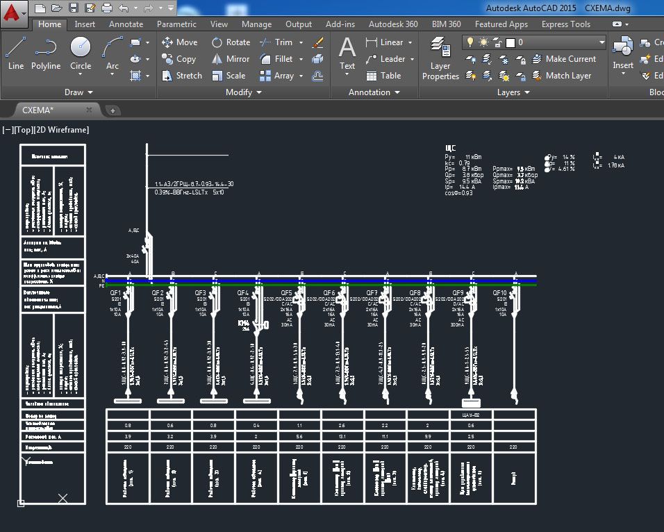
Work on drawing up a single-line diagram of a switchboard in AutoCAD Electrician
Video: tips from an experienced electrician
In this video, we will tell you how to make a single-line power supply scheme for a house based on a three-phase switchboard.

And if you have questions for the author of the article, do not hesitate to leave them below in the comments.


See also:
 Wiring diagram of a pass-through switch with 2 places: how to organize system control
  How to choose the right cable channels: types and sizes of wires
  DIY saving: repairing LED lamps
  Which electricity meter is better to put in an apartment - expert advice
  How to take readings from an electricity meter, what to look for and how to calculate tariff payments
  Profile for LED strip - purpose and scope


